In memory of
Flying Officer (RCAF)
Robin John Zemek
July 20, 1967
Rastatt, Germany
Military Service:
- 97020
- 25
- Air Force
- 421 Strike/Attack Squadron
Additional Information:
- February 9, 1942 Portsmouth, England
- May 14, 1963
-
- Son of James and Margaret Zemek.
- Husband of Sheryl B. Zemek.
- Brother of Ruth and Edwin Zemek.
- Father of Darryl Zemek (born 1966)
__________________


- INFO on 421 Strike / Attack Squadron
- INFO on History of 421 Squadron
- INFO on "The Story of 4 Wing"
- INFO on 421 Strike / Attack Squadron and Nuclear Armaments that the CF104 Starfighter Carried (Google Books / Canada's Nuclear Operations)
__________________
Flying Officer Robin John Zemek - Died in #104875 on July 20, 1967 / 4 Wing Baden. Germany
 The accident narrative simply reads "Aircraft pitched up due to pilot disorientation. Pilot ejected but sustained fatal injuries due to seat malfunction. F/O RJ Zemek F"
Mark: For many years I've always wanted to find out exactly what the difficulty was in the ejection seat that seems to have lead to his fatality. It was only recently that a friend let me know that the aircraft Robin was killed in was a CF104, and I confirmed this with Sheryl, Robin's widow in a phone call. I thought that perhaps through talking to some Starfighter guys I could find out more about his accident. So, I joined the FACEBOOK PAGE "CF104 Starfighters" Group. This group bills their objectives for starting a Facebook Group simply as follows:
"Thought it would be great to have a gathering place for any former CF-104 pilots, techs and enthusiasts. "
So I posted on this Facebook Group's Page to attempt to find some info:
___________________________________
Flying Officer Robin John Zemek - Died in #104875 on July 20, 1967 / 4 Wing Baden. Germany
The accident narrative simply reads "Aircraft pitched up due to pilot disorientation. Pilot ejected but sustained fatal injuries due to seat malfunction. F/O RJ Zemek F"
I met Robin many years back at his wedding reception when I was probably about 9 or 10 years old. He married my cousin.
If anyone has pics of 104875 or Robin John Zemek, please send them my way. I'm a commercial pilot, and find no end of enjoyment in the least bit of trivia, family info, technical or general interest alike. (Robin also had an accident in 104867 nine months before his fatal 104875 accident & pics of that would be great.) I've looked through some of the photos here, and have noticed the photos of the sister ships to #875. Finding the actual one would be cool.
Thanks for adding me to this Facebook Group. Fascinating pics and information here!
Cheers! Mark
Georgetown, Ontario
Georgetown, Ontario
___________________________________
The following is excerpted from my online chatting with (as I find out) are people who not only worked in the same 4 Wing at Baded as Robin, but also assisted in the accident investigation of his accident. (Steve Pajot).
Mark: Here are a few pictures I have at the Canadian Starfighter Museum in St. Andrew's Airport, Winnipeg, Manitoba. We are currently restoring the first CF104 Starfighter to have flown in Canada RCAF serial # 12703. You can view our website at www.canadianstarfightermuseum.
I am the curator and founder of this museum and the CF-104 has always been dear to my heart since I was a young lad based in 4 (F) Wing Baden-Soellingen, West Germany 1964-69. I eventual ended up an honorary member of 417 TAC F OT Squadron at Cold Lake, Alberta and flew in the CF-104.
An interesting side note is that I was one of the people who were sent out in search of F/O Zemek's pilot's helmet after the crash of 12875 as the RCAF wanted to see the helmet to determine the cause of F/O Zemek's death. This helped to determine that the seat/pilot separation did not function as it should have after the ejection form the aircraft. I also have a small piece of the wing section from that crash.
Cheers Steve Pajot
Curator Canadian Starfighter Museum
St. Andrew's Airport, Winnipeg, Manitoba CANADA


Robin also had an accident in this aircraft 104867 on October 28, 1966. The accident report read: "Aircraft pitched up during handling exercise. Pilot ejected safely. Flying Officer, RJ Zemek non-fatal"

Here is 104875 (Robin's fatal accident aircraft).
___________________________________
Fabulous! Thanks so much for these pics. The next time I have some time in Winnipeg, I will head out to see your museum. Also, I've always wanted to find out exactly what the difficulty was in the ejection seat that seems to have lead to his fatality. Perhaps talking to some Starfighter guys will solve that.
Thanks again, regards, mark
___________________________________
Mark: Drop by anytime to have a tour. I am the curator...Steve Pajot
Apparently Robin ejected in a Pitch-up configuration which is the coffin corner in an F-104 Starfighter. It results in a flat spin and because of the high "T" tail the stall blanks out the tail. The Pitch-Up is almost non-recoverable unless perhaps you have a lot of altitude available and a little luck on your side. Robin ejected after loosing situational awareness which resulted in the Pitch-Up and to make things worse he was in cloud during a terrific thunderstorm.
The C2 ejection seat performed properly and he did descend in his parachute but he incurred fatal head injuries. Finding the DH-41 helmet which was in use at that time by the RCAF helped determine the probable cause of his death. It is thought that the pilot and seat separated as advertised but that in the turbulence of the storm the seat and the pilot collided after separation and most likely the helmet was torn from his head after the canopy was jettisoned.
This is one reason why the RCAF eventual went with a dual visor modification to the DH-41 helmet ( DH-41-2 helmet ). It was advised that aircrew fly with the clear visor down at all times but at least to drop the clear visor prior to ejecting. As you can appreciate the Starfighter is a high performance and a high speed aircraft and with the canopy leaving prior to the seat moving up the rails during the ejection sequence the slipstream would be quite violent.
Hope this helps you better understand what had happened. My heart goes out to his wife and son. I always felt close to this particular accident because I was there on the Base at that time and I had participated in the search to find his helmet. Because of this I did some research on the accident to help myself better understand what had happened.
Cheers, Steve CSM
____________________________________________________________________
Another CF104 technical guy comments further on what probably transpired post-ejection:
From what I remember the emergency oxygen line,was attached to the parachute and to a small O2 bottle in the bottom edge of the parachute. To activate it, a "green" apple knob was on the end of the cable for the pilot to pull. I think the green apple got tangled somehow in the arm restraint webbing on the seat and kept the seat in contact with him after ejecting.
The green apple was modified to add a quick release snap between the cable and the ball. i was in Lahr at the time and our safety systems guys were busy modifying all the parachutes shortly afterwards. I am pretty sure this was the accident in question. If not then my apologies. Gary Watson

Here is 104875 (Robin's fatal accident aircraft) on the ramp.
___________________________________
___________________________________________
Note: At 13 mins, in this video Dave Groark discusses the problem phenomenon of the CF-104 "pitch-up" scenario. At higher angles of attack (beyond the 4.5 deg. indicated angle of attack stickshaker warning) the T-tail is blanked-out by the fuselage/wing. In most cases this was not a recoverable situation, and the aircraft would begin to "somersault".
___________________________________________
Robin John Zemek Burial Information:
Choloy War Cemetery; Meurthe-et-Moselle, France
Grave Reference: Plot 4, Row J, Grave 7
Choloy is a village and commune in the Department of the Meurthe-et-Moselle, 28 kilometres west of Nancy and some 5 kilometres west of Toul, a town on the N4 road from Paris to Nancy. The village is south of the River Moselle on the minor road (D11B) from Toul to the neighbouring village of Foug. The CHOLOY WAR CEMETERY is 3 kilometres west of Toul on the north side of the D11B road. The Choloy War Cemetery is the last resting place of casualties from the First and Second World Wars and is managed by the Commonwealth War Graves Commission. It is also the final resting place for many Royal Canadian Air Force members and their families who died while serving in Europe as part of 1 Air Division between 1953 and 1967 and other Service Members serving with NATO in Germany following Canada's departure from France.
- Commemorated on Page 134 of the In the Service of Canada Book of Remembrance.
- Request a copy of this page.
Technical INFO:
International F104 Society - Pics and INFO
Period Research on Nuclear Warfare -F104 carried nuclear weapons
Period Research on Nuclear Warfare -F104 carried nuclear weapons
CF104 Ground Checklist - Last Chance Check
History of 4 Wing and INFO on BCATP:
"The Plan"- On the 10th of October, 1939, an announcement was made stating that Canada, the United Kingdom, New Zealand and Australia were in principle agreement to the establishment of the British Commonwealth Air Training Plan."
- On Dec 17 1939 , the agreement was finalized and signed thus the BCATP officially came into existence.
- 25 October 1942, RCAF Group 6 Bomber Command was formed.
Canadian bomber pilots and crews had been operating and flying missions from the start of the Second World War, but on this date a Canadian Bomber Group was at last formed. Though Group 6 did not start combat operations till January 1 1943 it is still a significant date as it marks the start of dedicated Canadian operations as a group.
Over 10,000 Canadians were lost in Bomber Command (all groups) during the Second World War in service to our country and in the effort to free Europe from the NAZI tyranny that had overrun a population of millions on the continent.
Picture if you will the many thousands of young Canadians that served in all Groups of Bomber Command, typically 18 to 22 years old, all volunteers. Flying into the black of the European night skies to be hunted by night fighters, shot at by huge 88mm diameter anti aircraft guns like ducks in a fall sky. Limited radio, no GPS, only very rudimentary radar and Navigation aids in aircraft with huge piston engines and construction techniques that had only been put into production short years before.
10,000...paid the ultimate price for freeing the European continent, 10,000 paid the price for Canada's place in today's world as an influence, a leader and as an example of freedom and democracy.
On the 70th Anniversary of Group 6 Bomber Command I would ask we all take a moment to think of all the young Canadians that challenged the dangers of Europe' night skies for freedom.
Europe’s Finest
On October 1 1952, No.1 Air Division Europe or simply known as the 'Air Div' was formed as part of the 4th Allied Tactical air Force with temporary headquarters on the Avenue Montaigne just off the champs-Elysees in Paris, France. A new permanent home was found at the Chateau de Mercy near Metz. At it's pinnacle, the 'Air Div consisted of 12 squadrons (8 flying the Canadair Sabre in the day interceptor role and four flying the Avro CF-100 Canuck in the all weather role)
The squadrons were divided between four Wings:
No.1 (Fighter) Wing Marville, France;
No.2 (Fighter) Wing Grostenquin, France;
No.3 (Fighter) Wing Zweibruken, Germany and
No.4 (Fighter) Wing Baden - Soellingen, Germany .
Also supporting the Air Division was
No.30 Air Material Base at Langar near Nottingham, England and
No. 61 Aircraft Control and Warning Squadron based a short distance from the Air Division's headquarters at Metz.
As of October 1 1962, slightly more than 6,400 RCAF personnel were assigned to No.1 Air Division, plus some 270 more at various higher NATO formations. It is estimated that roughly 25,000 Canadian officers, airmen and airwomen served in Europe in the preceding decade since No.1 Air Division's inception.
______________________________________________________________________
______________________________________________________________________
- Detailed History of F104 - From Conception to Production
- Starfighters Links
- International F104 Society
______________________________________________________________________
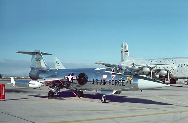
F-104
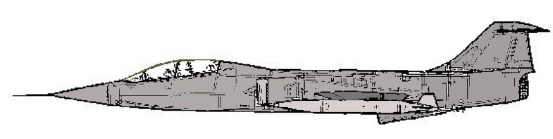
STARFIGHTER
A long time ago I added the HS-125 Hawker Jet to my list of Type Ratings. It was a Ho-Hum sort of an airplane, but I was collecting Type Ratings at the time, and the price was right. Some time afterward, I got a call from an old friend in Phoenix. He just got a Hawker on the line and nobody was qualified to fly it. I explained that I was very short on experience in that airplane, but would do what I could to help. After the pilots were trained, my friend asked how much he owed me. I said that I did not feel I should charge, as I was learning while teaching, and suggested that maybe he give me a couple checkouts in their T-33 instead. He said OK.
It was about 4 years later, and I had not gotten around to collecting my checkouts in lthe T-Bird. I was not worried, as Bill has always been a stand up guy, so I knew he would come through when the time came. I was ferrying an old Hawker to Texas for an inspection. It had not been flown in a couple of years, but we had all the proper paperwork from the Fed's, so we were legal. Maintenance said that they had flushed the fuel system as we requested. We did an extensive preflight, including draining a bunch of the new fuel, and off we went. While enroute, both airspeed indicators wound up making their way to the Zero mark. Yes, Zero! Oh well, I remember what it is supposed to feel like, so we weren't going to die or anything rash like that. Then, the left engine started to roll back slowly, The low fuel pressure light was on, and no amount of crossfeed or anything else was going to put it out. The engine continued to spool down and eventually quit.
I figured I had a fuel contamination problem. The other engine was as far as I was concerned, on borrowed time. I reduced the remaining throttle to Idle, thinking that this would allow the fuel filter on the other side to clog more slowly, and I might as well have bleed air, hydraulics and a generator. Deer Valley Airport, DVT, was within gliding distance and it was a clear day. I landed, and pulled up to my friends FBO where I had trained the Hawker Pilots.
After delegating the Hawker to their maintenance department, I noticed an F-104 parked on the ramp. I have always had the hots for the Starfighter. My dad worked on the airplane as an aeronautical engineer in the old days. As far as I was concerned, it was the ultimate bad ass airplane. Since the military wouldn't take us folk who wore contact lenses, I thought I would never stand a chance of flying an airplane that neat. Laser surgery did not exist for the public then. The P-51 was lots of fun, but not even close to the Starfighter.
I asked If I could trade my 2 checkouts in the T-33 for one checkout in the F-104. Bill said "no problem". Once we worked out the schecule and the necessary security checks, my dream did come true. I went through the manuals, and wrote this study guide as a means of learning the airplane. After the training, I was invited to join the team and fly it on some test missions. All the paperwork came through, but due to the defense cutbacks, thank you Bill Clinton, the company went broke.
Such is life, but the most important thing was that I did get to fly what I consider to be about the neatest thing on earth. Yes, there are faster airplanes now, but not much faster, but the Starfighter occupies a place in my mind and heart that only it can fill, and I feel very fortunate that the Lord saw fit to allow me the oportunity to fly it.
F-104 Starfighter
The Ultimate
Bad Ass Airplane
Wing span 21.94 Feet
Length 58.26 Feet
Height 13.49 Feet
Tread 8.79 Feet
Weight
Two pilots & Full internal fuel 19,500 lbs.
Two Pilots & Full fuel with tip tanks 21,750 lbs.
These are not maximum weights, as the aircraft may be loaded to in excess of 28,000 lbs. with additional external fuel tanks and weapons.
Vmo 750 KCAS *575 below 25,000 Ft if tip tanks have 16.5 inch vanes
Mmo Mach 2.0 Mach 1.9 With Tip Tanks
Vfe - Takeoff 450 KCAS / .85 Mach N/A blo 330 KIAS
Vfe - Extended or Retracting 520 KCAS / .85 Mach N/A blo 350 KIAS
Vfe - Land 240 KCAS
Vlo 260 KCAS
Vle 295 KCAS
CIT (Comp Inlet Temp) 121 deg C
Engine RPM 101% Without T2 Reset
104 % With T2 Reset
105 - 107% Overspeed 5 sec Max
EGT Limits 600 deg C for 30 min below 35,000 ft
600 deg C for 2 hours above 35,000 ft
560 deg C Max Continuous
Acceleration or Burner 660 deg C for 20 sec
635 deg C for 40 sec
615 deg C for 2 minutes
Start Limits 600 - 1,000 deg C
800 deg C for 6 sec
750 deg C for 8 sec
725 deg C for 13 sec
705 deg C for 20 Sec
Start Duration 60 sec Max IGN to Idle rpm.
SAS Fail 300 KIAS Max
Acceleration Limits Below 1.9 Mach + 7.33 / - 3.0 W < 5000 Int Fuel
Mach 1.9 or above + 4.50 / - 2.8 W > 5000 Int Fuel
Abv 1.9 M & FL 400 + 2.20 / - 2.8
Engine
The F-104 is powered by a GE J79 engine. The J-79 has a 17 stage axial flow compressor, and a three stage turbine. Maximum thrust is 15,800 lbs. in full afterburner, and 10,000 lbs. at military power. For reference, 100% = 7,460 rpm.
The inlet guide vanes on the first 6 compressor stages are variable, and are controlled by the fuel control for optimum engine acceleration. With the landing gear retracted, the # 2 hydraulic system opens 2 bypass flaps, allowing excess ram air to by-pass the engine. The exhaust nozzle is also variable. Like the inlet guide vanes, it operates automatically. The exhaust nozzle is equipped with a system that will enable you to close it to a setting of 2.5 in the event the normal system fails. This will not allow any further use of the afterburner, and will result in slightly higher thrust during landing.
Engine start requires an external air cart and ground power. Two start switches activate the two independent ignition systems. "ON" starts a 45 second ignition cycle, "Stop Start" terminates the ignition cycle. the switches are spring loaded to center which is "OFF". Air for the starter is controlled by the ground crew. It is initiated upon a signal from the pilot, and terminated when the pilot signals that the engine has reached 40% rpm.
Inflight engine starts are possible, as a windmilling J-79, as installed in the Starfighter will provide electrical power to the # 2 fuel boost pump even if the # 2 generator has tripped off line (below 65% rpm), because it will operate directly from the generator. Ignition is also available.
The engine fuel system uses a centrifugal booster pump and two positive displacement gear type pumps. Loss of the centrifugal pump may limit power during low altitude high mach operation. Loss of one high pressure pump will not cause engine failure, as the other pump can supply enough fuel.
Afterburner fuel is supplied by it’s own engine driven centrifugal pump. Engine rpm must be at least 94.6% to light the afterburner. There are 4 stages of fuel flow in the afterburner. They are (1) Primary sector, (2) Secondary sector, (3) Primary uniform, and (4) Secondary uniform. To insure positive ignition of the fuel, the pilot burner provides an intense flame via a fuel nozzle and spark plug. This system activates when you first select afterburner, and continues to operate until the engine is shut down.
ENCS
The "Emergency Nozzle Closure System", or ENCS, may be used to close the exhaust nozzle to about 2.5 if the speed is below 450 kts and 1.0 Mach should the nozzle fail. Power should be at 85 - 90% if possible. Burner will not be available. EGT may be as high as 700 deg C at military power, but should be kept at or below 560 deg C when possible to extend engine life. The system is electrically controlled, and powered by a nitrogen bottle. (Updated from the stock pyrotechnic charge system.) It is activated by a guarded switch on the lower left sub panel of the front cockpit.
T 2 Cutback
Supersonic aircraft engines must deal with a large range of airflow and inlet temperature. The by-pass flaps that open when the gear is up, allow ample excess air to flow around the engine such that the engine may more or less ingest what air it needs. Temperature is another matter. As the intake air gets warmer, there is a drop in density for a given pressure. Fuel control units take at least 4 variables into account when determining how much fuel to give the engine. They are: Compressor inlet temperature or "T2", Compressor discharge pressure, or "P3", Engine RPM, and Power Lever Angle. How hot, how much pressure, how much RPM, and how much thrust does the pilot want. The fuel control uses these variables to decide how much fuel is provided.
As the speed increases, the temperature increases, remember our old friend ram rise. As the air gets warmer, the density decreases. The engine then would not be getting as much air it thinks it’ getting at the same pressure. The fuel control, from 92 to 104 deg C inlet temperature, compensates for this by increasing rpm from 100 % to 104% to make up for the loss in density.
When the engine inlet temperature exceeds 105 deg C, something else changes. Don’t freak out if the engine rpm remains at 100% when you retard the throttle to idle. The CIT only gets to 105 deg C for one reason, you are going fast as hell, remember, that’s our old friend ram rise showing up. When you are going that fast, there is a lot of air being stuffed into the intake. The rpm must be kept high in order to ingest the air, or it will do the same thing you would do if you drink a warm coke to fast, it will burp! It, however will burp somewhat louder than you. We all refer to airplanes as females. They are less attractive when they burp. This one is designed not to. Don’t worry, as speed and CIT decrease, the rpm will again begin to respond to the throttle. This is all normal.
Electrical
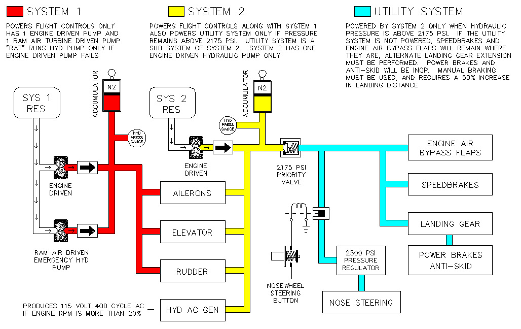
Lockheed did a nice job when they designed the electrical system on this airplane. It is equipped with two batteries, two engine driven variable frequency AC generators, a constant frequency 400 cycle AC generator, driven by the # 2 hydraulic system, and a ram air driven constant frequency generator for emergency use. DC power is produced by two 28 volt transformer rectifiers. You can still land safely if only the emergency generator is operating.
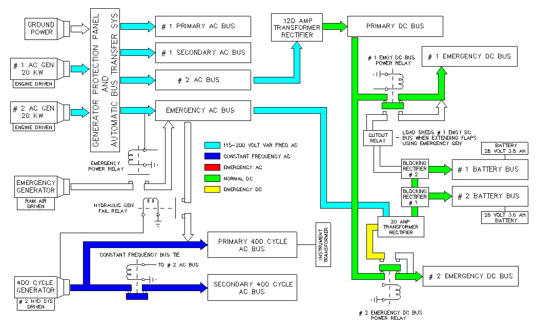 |
Two 20 kW generators, producing 320 to 520 cycle, 115 to 200 volt AC power are installed. The voltage and frequency depend upon engine rpm. For you physics freaks, each generator produces the electrical equivalent of a little over 25 horsepower.
The variable frequency AC generators will trip off below 65% rpm, about 2% below normal idle. The number 2 fuel boost pump will receive power down to 40% rpm, as it is tied directly to the generator.
The loss of one main generator results in loss of the # 1 secondary AC bus. The intake duct anti-ice, fuel transfer pump, and # 1 and # 4 boost pumps will be inop.
Constant Frequency Generator
The constant frequency 400 cps 115 volt AC generator is driven by the #2 hydraulic system. This little jewel can operate down to about 20% engine rpm. It provides power to the items that require constant frequency AC power. These items are on the primary and secondary fixed frequency busses. If the constant frequency generator fails, the busses will be powered from the emergency AC bus. In the event both main generators and the constant frequency generator fail, the secondary fixed frequency AC bus will be un-powered.
Ram Air Turbine Driven Generator
The "RAT", when deployed, drives the 4.5 kW 115 volt 400 cycle generator, as well as an emergency hydraulic pump. If all other generators fail, the "RAT" will power the emergency AC bus, primary fixed frequency AC bus, and through a 20 amp transformer rectifier, both emergency DC busses and the battery busses. The emergency AC bus will not power the fixed frequency AC bus as long as the hydraulic driven generator is operating.
Emergency AC Bus
In order for the Emergency AC Bus to be powered you must have one of the main generators, or the emergency generator on line. This bus does not load shed unless both engine driven generators and the emergency generator are inop.
Leading Edge Flaps # 3 Fuel Boost Pump
Training Edge Flaps` UHF Comm & Tacan
Windshield Defog Transponder
# 1 Emergency DC Bus
In order for the # 1 Emergency DC Bus to be powered by the primary DC bus, (gets it’s power from the 120 amp transformer rectifier), you must have one of the main generators on line. Otherwise, it is powered by the Emergency AC bus through a 20 amp transformer rectifier and the # 1 Emergency DC bus power relay. The # 1 Emergency DC Bus is un-powered when the flaps are operated during emergency electrical system operation. The items listed below are powered by the # 1 Emergency DC bus.
Landing Gear Indication Trim Control
Landing Gear Warning Warning Lights (Except Fire)
Landing Gear Control Rain Removal System
Rudder Limit Control Windshield Defogger
Speed Brakes Canopy Audio Warning
Stick Shaker Canopy Seal
Fuel Quantity Gauges External Tank Transfer
Hot Air Shutoff
Transponder
# 2 Emergency DC Bus
Number 2 Emergency DC Bus is powered by the # 2 AC Bus through the 120 amp transformer rectifier. If # 2 AC is not powered, the Emergency AC Bus powers it through the 20 amp transformer rectifier. Only two items are on this bus.
Leading Edge Flaps Trailing Edge Flaps
# 1 Primary AC Bus
In order for the # 1 Primary AC Bus to be powered you must have only one main generator on line. The inertial navigation heater is the only item on this bus. This is of little concern, as the INS will have most likely been removed and replaced with a smaller and lighter GPS unit, or just a Rolex and a compass.
Primary DC Bus
The primary DC bus is powered by the # 2 AC Bus through the 120 amp transformer rectifier. During normal operations, it in turn powers the # 2 Emergency DC bus.
Air Data Computer Seat Actuator
Auto Pilot Cockpit Spotlights
Nav Lights Duct Anti - Ice
Electronic Equipment Test Engine Air by-pass Flaps
Taxi Light Engine Inlet Air Temp
Radar Accelerometer
Voice Recorder Radar Dehydrator
# 1 Secondary AC Bus
Powered by main AC generators if they are both operating and on line.
# 1 Fuel Boost Pump Intake Duct Anti - Ice
# 4 Fuel Boost Pump Transfer Pump
# 2 AC Bus
Powered if at least one of the main AC generators are operating and on line. Loss of both main generators will render this bus un-powered.
Afterburner Ignition Optical Sight
Air Conditioning Oxygen Indicator
Anti - Icing Valve Pitot & AOA Probes
# 2 Fuel Boost Pump Auto Transformer for LDG Lights
CIT Warning System Radar System
Primary Fixed Frequency AC Bus
Afterburner Nozzle Indicator Cockpit Panel Lights
Auto Pitch Control Cockpit Flood Lights
C-2G Compass Standby Attitude Indicator Instrument Power Transformer Tacan & IFF
Secondary Fixed Frequency AC Bus
This bus is load shed if power to the # 2 AC Bus is lost. Loss of both main generators will make this happen.
Air Data Computer Stability Augmenters
Auto Pilot Fuel Indicators
Radar System Voice Recorder
# 1 Battery Bus
Powered by the Emergency AC Bus through the 20 amp transformer rectifier or by the # 1 battery.
Engine Start # 1 External Power Control
External Stores Release Fuel Shutoff
ENCS Emergency UHF Radio
Anti - Skid Nosewheel Steering
Engine Oil Low Warning Special Stores Drop # 1
# 2 Battery Bus
Powered by the Emergency AC Bus through the 20 amp transformer rectifier or by the # 2 battery.
Engine Start # 2 External Stores Emgy Release
External Tank Refueling Fire Warning System
Arresting Hook Main Generator Reset
ENCS Special Stores Drop # 2
Fuel
The fuel system is designed so that the pilot must do little else but make sure it is full to start with, and that it is not empty before landing. Normal VFR reserve for this airplane is 1,000 lbs. of fuel. Starting with full internal and full tip fuel, the aircraft will go about 750 nautical miles. If you stay in burner and go fast, you are out of gas in less than 30 minutes.
Internal Fuel 5,746 lbs. 6,516 lbs.
Tip Fuel 2,210 lbs.
Total Fuel (Int. + Tips) >> 7,956 lbs. << 8,726 lbs.
Total Fuel (Int. + Tips + Pylons) 10,490 lbs. 11,260 lbs.
The extended range fuel system consists of individual fuel tanks located in the gun compartment, case stowage compartment, and forward of the Fwd main fuel tank. Operation is automatic, requiring no pilot action.
Aft Center Tank - The aft center tank transfers it’s fuel to the Fwd Main Tank. The aft center is kept full first by the pylon tanks, then by the tip tanks until they are empty. This transfer is automatic, and will continue in the event of electrical failure.
Left & Right Aft Tanks - The aft tanks transfer their fuel to the aft center tank through bottom tubes. The top tubes serve as vents.
Pylon Tanks - Mounted under wings on pylons. Transfers to aft center tank prior to tip tank transfer.
Note:
If absolute maximum range is a must, the pylon tanks, pylons, and the tip tanks may be jettisoned in order to reduce drag and increase range after they are empty (or before if necessary). This is not recommended, as your local FBO may not stock F-104 gas tanks, and it tends to create a high stress environment among people on the ground. Most non pilots just can’t cope with this kind of pressure without exhibiting some form of hostile or otherwise irrational behavior.
Fuel Boost Pumps - Four electric fuel boost pumps are installed to provide positive pressure to the engine driven fuel pump. They provide 20 to 26 PSI and are powered by the AC electrical system. They are located in the Fwd Main fuel cell. A low fuel pressure warning will come on below 12 psi.
The # 1 and # 4 Boost pumps are powered by the # 1 Secondary AC Bus. As long as the # 1 and # 2 Generators are working, these pumps are powered. If either of the generators fails, these pumps fail. The # 2 and # 3 pumps will continue to run, as they are powered from alternate sources.
The # 2 Boost pump is normally powered by the # 2 AC Bus. If the engine rpm goes below 65%, the # 2 boost pump is powered direct from # 2 Generator. This works down to about 40% rpm in order to allow high altitude engine re-lights.
The # 3 Boost pump is powered from the emergency AC bus. The emergency AC Bus will be powered if there is any AC power source operating on the airplane.
Hydraulics
The Starfighter has two independent hydraulic systems, in addition to an emergency system. The two main systems each operate at 3,000 psi. Both have accumulators that are precharged to 1,000 psi to dampen surges in their respective systems.
# 1 Hydraulic System - 3,000 psi
Aileron Actuators
Stabilizer Actuators
Yaw Damper Control Valve
The Autopilot actuators for the ailerons and stabilizer, the auto pitch actuator, and the yaw damper control valve are powered by this system. Autopilot won’t engage below 1,250 psi. A low pressure warning illuminates below that value.
Emergency Hydraulic System
The emergency hydraulic system, as it is called, consists of a ram air turbine that may be extended by the pilot in the event the # 1 hydraulic system pressure s lost. This ram air turbine powers a hydraulic pump that takes fluid from the # 1 Hydraulic Reservoir, and pressurizes the # 1 Hydraulic System as long as the ram air turbine is up to operating rpm. This is the same ram air turbine that powers the emergency generator. It only powers flight controls.
# 2 Hydraulic System - 3,000 psi
Flight Controls
Constant Frequency AC Generator
Pitch & Roll damper control valves
Unpowered below 2,175 Psi If Unpowered
* Landing Gear Manual Gear Extension
* Normal Brakes Manual Brakes
* Anti-Skid Inoperative
* Nosewheel Steering Diff Braking & Rudder
* Engine Air by-pass Flaps Fails in last position
* Speedbrakes Fails in last position
* Denotes "Utility" items. If # 2 Hydraulic System pressure drops below 2,175 psi these items become unpowered such that the remaining pressure powers the flight controls and the Constant Frequency 400 cycle AC Generator.
 |
Normal landing gear operation is electrically controlled, and hydraulically actuated from the # 2 hydraulic system if pressure is above 2,175 psi. Gear extension or retraction takes 4 to 5 seconds. Up or down may be selected anytime speed permits, even if the gear is in transit. If normal gear extension is not available for any reason, the gear may be extended by pulling the yellow "MAN LDG GEAR" handle out about 10 inches to the stop. Alternate gear extension should be performed below 225 kts, as the nosewheel may not lock down at higher speeds, and may collapse during the landing roll. Alternate gear retraction is not possible. The landing gear handle is equipped with a trigger to prevent inadvertent extension.
A gear warning light will illuminate whenever the gear is not in the selected position. A horn will sound below engine rpm 100%, altitude less than 10,000 MSL and IAS below 220 Kts.
Nosewheel Steering
The nosewheel is steerable 25 deg right or left of center. Steering is provided by a steer-damper unit that gets hydraulic pressure from the # 2 Hydraulic system as long as pressure remains above 2,175 psi. The hydraulic fluid is routed to the steering system through a solenoid shut-off valve, (engaged by the pilot via a button on the front of the stick), a filter, and a pressure reducing valve, lowering the pressure to 2,500 psi. Forces on the nosewheel are not transmitted back to the rudder pedals. Disengage nosewheel steering prior to rotation on takeoff to insure proper steering clutch release. On landing, engage nose steering after nosewheel is firmly on the ground. Do not engage nosewheel steering if # 2 Hydraulic system fails. Air may enter the system and a violent shimmy can result.
Normal Brakes / Anti-Skid
The normal brake system uses # 2 Hydraulic system pressure as long as that pressure remains above 2,175 psi. Anti-Skid protection is provided by a system using a DC generator in each main wheel to provide wheel speed information to the system. When a sudden drop in wheel speed signals an impending skid, the brake pressure to that wheel is released. When the wheel returns to normal speed, the brake pressure is re-applied to the brake.
Failure of the Anti-Skid brake safety circuit may cause a "NO BRAKES" situation even though the system is otherwise normal. The brake pedals will feel normal, but no braking will occur. In this case Manual Brakes must be selected on the left forward console provided you still wish to stop.
Manual Brakes
The manual brake system uses pressure generated by the brake actuating cylinders as a result of foot pressure on the brake pedals, just as on many light aircraft. Plan on a 50% increase in landing roll. No Anti-Skid protection is provided. Manual brakes will operate whenever:
Selected by the Pilot with the switch
Anti-Skid fail safe circuit selects them
Loss of Electrical power
# 2 Hydraulic Pressure below 2,175 psi
After Manual Landing Gear Extension
If normal brakes do not work, don’t waste available runway determining why. Deploy the chute, select manual brakes, and stop the aircraft. You don’t have time to be a diagnostic wonder while using up the runway at 150 kts.
Speedbrakes
The speedbrake system consists of two panels, one on each side of the fuselage just aft of the trailing edge of the wing. They are electrically controlled by a switch on the throttle. The speedbrakes will fail to the retracted position in the event of electrical failure. If the # 2 Hydraulic system pressure drops below 2,175 psi, the speedbrakes will remain in their last position. Do not deploy the speedbrakes during landing or taxi, as temporary loss of directional control may result.
Drag Chute
An 18 foot diameter drag chute is provided to reduce landing distance and brake wear. It is stowed in the lower aft fuselage. A shear link will break, releasing the chute, if deployment occurs above 200 Kts. Do not deploy the Drag Chute unless the nosewheel is on the ground, and the engine is at idle.
Arresting Hook
The arresting hook is deployed by pressing the "Hook Release" button on the left windshield sill. The hook may not be retracted from the cockpit. No, they don’t land Starfighters on carriers, as approach speed is 170 Kts, and minimum touchdown speed is at or above 150 Kts.
Flight Control System
The flight controls on the F-104 are hydraulic. Because the controls are irreversible, aerodynamic loads are not felt in the stick. The control feel is artificially generated by a system of cams and springs. In the event of total loss of hydraulic power, you must eject. The ailerons and rudder are equipped with a limiting system that restricts their deflection when the gear is up.
Gear Up Gear Down
Aileron 9.75 deg 20.0 deg
Rudder 6.00 deg 13.0 deg
Normal and alternate trim are provided. Do not use trim without hydraulic power. The trim system merely re-defines the neutral position of the respective controls. Normal aileron and rudder trim are operated via a thumb switch on the control stick. Rudder trim is set with a toggle switch on the left side console. The Aux trim control panel is located in the aft portion of the pilot’s left side console. Trim position indication is limited Elevator, Aileron and Rudder takeoff trim position lights. These lights will illuminate Green when the trim is operating and is in the takeoff range. The lights go out when the trim is not running. There is an elevator takeoff trim range depicted on the tail. For alternate trim control, use switch panel located toward the aft end of the pilot’s side panel.
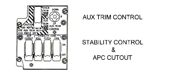
A Stability Augmentation System improves the aircraft’s handling characteristics about all three axes. There is no feedback to the stick from the "SAS" system. Roll, pitch and yaw stability control switches are located on the left console. Turning any one off will disengage the Autopilot. These switches should be left "ON" unless there is a malfunction. If SAS system fails, limit airspeed to 300 kts.
Stall Warning System
A stick shaker is installed to alert the pilot to an impending stall. It and the Kicker sense flap position to eliminate false warnings during maneuvering with flaps extended. The remaining switch on that console is the "APC" or "Kicker" . The kicker should be left on unless a problem exists. The "APC" will not work with the gear down or with landing flaps.
Wing Flap System
What little wing that is installed on the F-104 is equipped with Leading Edge and Trailing Edge flaps such that subsonic landings may be made. They are extended electrically, using variable frequency AC from the Emergency AC bus, and are controlled with a single lever. Two leading edge, and two trailing edge flap actuators are installed. With one actuator out, the leading edge flaps may be extended to takeoff at or below 370 kts, and retracted from land to takeoff at or below 230 kts.
Leading Edge Trailing Edge
Takeoff 15 deg 15 deg
Land 30 deg 45 deg
A safety feature prevents inadvertent flap retraction from Flaps Land directly to the UP position. On a go-around, flaps are retracted to Takeoff, then the gear is retracted. In order to retract the flaps, the flap lever must be pulled aft about 1/4 inch prior to placing it in the up position. During temporary disengagement of the pilots brain, this might prevent the airplane from going "SPLAT" at some random location on or about the airport.
When operating on the emergency air driven generator, the leading edge flaps will not extend to the takeoff position until the trailing edge flaps are finished moving. This reduces the electrical load on the system. The # 1 Emergency DC Bus is unpowered during flap operation on emergency generator.
Flap asymmetry protection is provided for trailing edge flaps. At 5 deg differential, flaps will stop. In this case, return the flap lever to it’s last position and land.
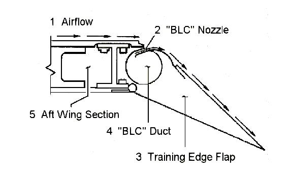
The valve that controls this is mechanically driven by the flap actuator, thus is always in the proper position. After a go around, leave the flaps in the takeoff position for 30 to 60 seconds to let the BLC system cool. Damage to the system will result if you forget this.
Auto Pilot

CSS or "Control Stick Steering" is available. Exert about 2.5 lbs. of force on the control stick, and the "AFCS" will change the attitude of the aircraft about the pitch or roll axis without disengagement of the Autopilot.
Canopy
Each canopy is a single piece of transparent plastic mounted in a frame that is hinged on the left side. Normal operation of the canopy is manual. The canopy may be jettisoned in an emergency with the jettison handle on the left side of the cockpit, or automatically when the ejection seat is fired. Major bummer if that one failed to work. When jettisoned, the canopy is released from both sides by the unlatching thrusters. They in turn fire the canopy ejection thrusters on the forward bottom of the canopy frame. The canopy is now hinged at the upper rear, causing up and aft rotation to insure that the canopy does not get in the way of your head, as it is launched skyward and compressed into your shoulders when the ejection seat begins it’s short flight.
Ejection System
The F-104 is equipped with a rocket propelled, upward ejection seat. Safe ejection is possible from ground level between 90 and 520 kts. Pilot departure from the ejection seat, and chute deployment are automatic. Chute deployment will occur shortly after passing 14,500 MSL, or about one and a quarter seconds after ejection at lower altitudes.
Environmental System
Air conditioning, pressurization and windshield de-fog use 17th stage bleed air from the engine. The bleed air passes thru the primary heat exchanger. Air pressure is diverted to the fuel tanks and hydraulic reservoirs to provide head pressure. The air then passes thru the bleed air shut-off valve. Some air is diverted for :
Rain Removal Radar Pressurization
Gun Comp Purge Canopy Seal
The remaining air is used to de-fog the windshield and to pressurize and air condition the pilot compartment. Temperature control is achieved with a rheostat for automatic or, in the event the automatic system fails, a toggle switch for manual control. Do not use manual unless automatic is inop. Both methods control a heat exchanger by-pass valve, and a cooling turbine by-pass valve.

 |
The defogger system causes warm air to flow over the inside surfaces of the canopy and windshields. The air normally comes from just downstream of the secondary heat exchanger and water boiler. If the demand on the defog system is high, a differential relief / check valve opens, and augments the defog air with hot bleed air from downstream of the primary heat exchanger and bleed air shutoff valve. This should provide enough defogging for any situation.
Rain Remover
The rain removal system receives bleed air from the same supply line that pressurizes the canopy and radar compartment seals. The air is routed through a pilot controlled shut-off valve to a nozzle at the base of the left windshield. This system is designed for use at low speeds. Use at high speed may damage the nozzle or crack the windshield. If not used in flight, purge the rain removal system for 30 seconds during taxi after clearing the active runway.
Anti-Ice
The Engine / Duct Anti-Ice switch opens the engine, anti-ice valve, providing 17th stage bleed air to heat the engine front frame and inlet guide vanes. The bottom strut is heated by scavenge oil from the engine oil system. The same switch causes the shock cones and inlet scoops to be electrically heated, providing de-ice and anti-ice capability. A thermal switch will illuminate the "ENGINE / DUCT ANTI-ICE ON" warning light when the temperature in the system reaches 163 deg C. The light may remain on for 30 seconds after the system is turned off, as there is still hot air in the duct.
The engine can safely ingest ice up to about 88% rpm. At higher rpm, the inlet guide vanes may be damaged. Engine anti-ice should not be use when the CIT is more than 10 deg C, as ice will not form at that temperature, and it shortens the life of the engine.
The "WINDSHIELD PITOT - PITCH TEMP PROBE" switch applies AC electrical power to the auto pitch control & stick shaker vanes, the pitot head, free air temperature probe, and to a thermostat that heats the left windshield panel to about 38 deg Centigrade. Do not operate this system for more than four minutes on the ground.
Flight
This aircraft, due to it’s performance capability, demands that you plan ahead, and pay full attention until it is shut down at the end of the flight. To quote the words of an old friend "It’s an honest airplane, If you make a mistake, it will kill you." Like any "Cook Book" flight profiles, these are not the only way to fly the airplane, but are time tested, and they work.
Start
Ignition Start Sequence - Initiate
Signal ground crew to initiate airflow
At engine rotation - Throttle Mil power then Idle
1 Finger at 10% rpm (Fuel Flow 450 - 700 pph @ 10 -12% rpm)
2 Fingers at 20% rpm
3 Fingers at 30% rpm
4 Fingers at 40% rpm (Air is disconnected at this time)
Note: Normal idle is 67% rpm, 8.5 - 9.0 Nozzle, 12 psi minimum oil pressure, Fuel Flow 1000 - 1300 pph, and EGT 220 - 420 deg C within 60 sec.
Signal GPU disconnect
Check ships generators on line
1 Finger - Ground crew checks Speed Brakes
2 Fingers - Ground crew checks Stabilizer, Aileron & Rudder
3 Fingers - Ground crew & pilot check trims in takeoff position
4 Fingers - Ground crew & pilot check APC shaker & kicker
5 Fingers - Ground crew checks flaps & "BLC"
Recheck TRIM, FLAPS & SPEEDBRAKES
Ejection seat safety pin - Remove & Stow
Taxi / Before Takeoff
Nosewheel Steering - Engaged & Checked
Brakes Power & Manual - Check & set to Power
Mil power 100%
Check Fuel Flow
Reduce to 80 % slowly
Reduce to idle rapidly
Takeoff
Nosewheel Steering - Engaged
Advance to Mil Power - 10 sec max acceleration time
Check Nozzle 7.5 - 9.5
Afterburner - Minimum Sector - Full when lit
Disengage Nosewheel Steering about 120 kts
Rotate at 170 kts - Liftoff will occur about 190 kts
Gear Up - Complete before 260 kts
Flaps Up - 300 kts (240 kts minimum)
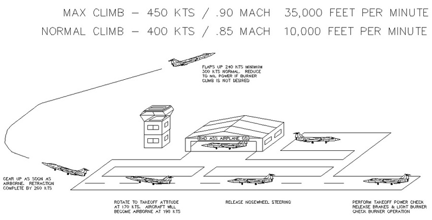 |
Mil Power climb 400 kts 0.85 Mach 12 deg nose up
Max Power climb 450 kts 0.90 Mach 38 deg nose up
The following table will give approximate time distance and fuel from brake release, sea level to 35,000 feet at a takeoff weight of 19,000 lbs.
Time Fuel Distance Sea Level Climb Rate
2 Min 20 Sec 1,025 lb. 12 N.M. 35,000 Feet / Min
6 Min 10 Sec 875 lb. 57 N.M. 10,000 Feet / Min
You heard of an "E Ticket Ride", this is the "F Ticket Ride", F-104 that is. Leaving the tip tanks home will give you only a slight increase in climb performance at the same weight.
Above 35,000 ft Mach 1.7 seems to give the best high speed climb performance. Acceleration to 1.7 Mach at this altitude takes 4.2 Minutes, 1,500 pounds of fuel and 50 nautical miles. To go from 35,000 ft to 50,000 ft at 1.7 Mach takes 3.1 minutes, 1,000 lbs fuel and 55 nautical miles. The initial climb rate at FL 350 is just barely 12,000 fpm. To accelerate on up to Mach 2.0 requires another 4 minutes, 500 lbs fuel and 75 miles. So, brake release to fifty thousand feet & Mach 2 takes 13.5 minutes, 192 miles and 4,025 lbs fuel.
Supersonic Flight
This airplane seems to perform best at around 35,000 feet. If you start at 22,000 lbs. and .90 Mach at this altitude, it will require 1,100 lbs. fuel, 4.5 minutes and 54 nautical miles to reach 1.5 Mach. It will do a bit better if the tip tanks are not installed. Fuel flow during this acceleration is about 14,500 pph. Afterburner fuel does not register on the fuel flow gauge. As you transition into the high mach numbers, monitor "CIT", (compressor inlet temperature), as that is what limits the maximum speed of this airplane at altitude.
Maneuvering
Because of it’s stability characteristics, the Starfighter has some aileron roll limitations. If you limit aileron rolls to 360 deg (one at a time), and maintain a positive load factor of 1/2 G or more, no stability problems should result. As far as the pitch axis is concerned, make smooth control inputs until the desired load factor is achieved, observe the G limits of the airplane, and heed the warning of the Stick Shaker and Kicker. During aggressive pitch changes, there is considerable rotational inertia about the pitch axis. This may cause over rotation and temporary loss of control if the control input is excessive, or to abrupt. You don’t get the best performance out of airplanes by jerking them around.
Cruise
Altitude for maximum endurance is variable, depending on the weight of the aircraft. Consult the table below to get an idea of how long you can remain airborne.
Weight Altitude Mach TAS Fuel Flow Time / 1,000 lbs.
23,000 lbs. 25,000 ft .84 M 510 kts 3460 pph 17.5 min
20,000 lbs. 28,000 ft .83 M 495 kts 3010 pph 20.4 min
17,000 lbs. 32,000 ft .84 M 490 kts 2400 pph 24.3 min
If you figure it takes about 1,000 lbs. to get to altitude, and you land with 1,000 lbs. reserve, that leaves about 6,000 lbs. of fuel to cruise with. Being on the realistic side, from takeoff to touchdown the time should be about 1.8 hours if you don’t experience delays or poor handling on departure or arrival.
Descent
The aircraft will usually descend anytime the pilot sees dirt out the front windshield. The rate of descent, distance covered and fuel used depends on the attitude and thrust used. For optimum descent performance, idle power and an airspeed of 300 kts is recommended. This results in 5,600 fpm, or about 1,000 feet per mile in clean configuration. A normal descent from 40,000 feet will take between 7 and 8 minutes, and consume about 70 pounds of fuel. With speedbrakes extended, the rate of descent is increased to 11,500 fpm, or about 2,000 feet per mile. This way, the same 40,000 feet is lost in 3.5 min, using 35 lbs of fuel.
Remember to anticipate your level off, as you can’t pull a whole lot of G’s at 300 kts clean. Don’t forget to increase power to maintain forward speed after level off. It takes a lot of energy to maintain 300 kts. When you are no longer descending, (using up potential energy) the power to maintain level flight must come from the engine. If you forget this, you will be subjected to a four phase aeronautical process that dates back to the early 1900’s. Stall, spin, crash and burn. Phase 4 requires some amount of fuel on board at time of impact.
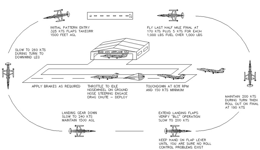
Landing
Landing distance of the F-104, like any other aircraft, depends on weight , elevation, and temperature. At sea level & 15 deg C, total distance from 50 feet to stop is about 5,000 feet. Ground roll is about 2,500 feet. This is providing all systems are operative. Increase total distance by 50% if using manual brakes. Add about 2,000 feet for landing with Takeoff Flaps and no Drag Chute. Climb rate in landing configuration at Mil power is 2,500 to 3,000 feet per minute.
Over fly runway at 1500 ft AGL, 325 kts and flaps "Takeoff"
Gear Down - below 260 kts
Flaps "Land" - 210 to 240 kts
Note: Keep your hand on the flap lever until proper flap extension and Boundary Layer Control system operation is verified. If significant unwanted roll is encountered, return flaps to their last position immediately
Maintain 200 kts during turn to final
Fly final approach at 170 kts + 5 kts per 1,000 lbs fuel over 1,000 lbs.
Note: Do not reduce power to less than 82% until touchdown, as the stall speed will increase due to the loss of air to the "BLC". Unwanted roll will also result as the engine decelerates unless you are on the ground.
Touchdown 150 kts minimum
Throttle - Idle
Nosewheel on ground
Nosewheel Steering - Engaged
Drag Chute - Deploy
Brakes - as required
 |
Radar & Transponder - Off
Flaps - Takeoff
Speedbrakes - Deploy
Engine Anti-Ice & Pitot Heat - Off
Rain Remover - Purge 30 sec then Off
.
Go Around - 200 to 300 lbs. fuel required
- Apply Military power, or Afterburner if appropriate.
- At or above 170 kts, Flaps Takeoff.
- Landing Gear Up (Complete retraction prior to exceeding 260 kts)
- Leave flaps at Takeoff for about 1 minute to cool "BLC" vanes.
- If remaining in pattern, leave flaps in Takeoff position.
- Departing, Accelerate to 240 - 300 kts, Flaps 1/4 inch down then UP
- If remaining in pattern, leave flaps in Takeoff position.
Shut down
Ground crew checks:
No comments:
Post a Comment